
The PS/2 interface was introduced by IBM with the Personal System/2 line in 1987, replacing the older 5-pin DIN (AT) keyboard connector with a 6-pin mini-DIN. The standard connector carries Data on pin 1, Ground on pin 3, +5 Vdc on pin 4, and Clock on pin 5; pins 2 and 6 are reserved and normally unconnected. Certain laptops and desktop systems expose a single combo PS/2 port that routes a second PS/2 channel through the reserved pins, enabling a Y-adapter to split the port into independent keyboard and mouse sockets. The Gateway variant uses an inverted convention: the keyboard female receives the computer’s Data and Clock signals via pins 2 and 6 rather than the standard pins 1 and 5, whilst the mouse female receives the computer’s reserved-pin signals on its own pins 2 and 6.
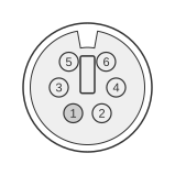 6 PIN MINI-DIN MALE (PS/2 STYLE) to the Computer
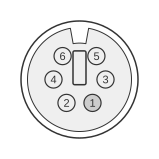 6 PIN MINI-DIN FEMALE (PS/2 STYLE) to the Keyboard
6 PIN MINI-DIN FEMALE (PS/2 STYLE) to the Mouse
| Computer | Keyboard | Mouse |
|---|---|---|
| 1 | 2 | - |
| 2 | - | 2 |
| 3 | 3 | 3 |
| 4 | 4 | 4 |
| 5 | 6 | - |
| 6 | - | 6 |
Signals
- Data — bidirectional serial data line; open-collector, pulled to +5 Vdc; idle high
- Clock — clock generated by the device; open-collector, pulled to +5 Vdc; 10–16.7 kHz; idle high
- Ground — signal and power return (pin 3 on all connectors)
- +5 Vdc — supply voltage 4.5–5.5 V; maximum device current 275 mA (pin 4 on all connectors)
- Not Implemented (pins 2, 6 on standard ports) — repurposed by this Y-adapter to carry the second PS/2 channel; function is host-hardware dependent and not defined in the base IBM PS/2 specification
Notes
- The host port must have hardware support for the combo mode; not every single PS/2 port carries a second channel on pins 2 and 6.
- The Gateway wiring convention is the inverse of the ThinkPad/Compaq convention. On a ThinkPad Y-cable the mouse is straight-through on pins 1 and 5, whilst the keyboard uses the reserved pins. Here the keyboard occupies pins 2 and 6 of the computer connector and the mouse occupies the same reserved pins on its side.
- Data and Clock lines use open-collector drivers; the host pulls both lines high via pull-up resistors (typically 1–10 kΩ). Maximum sink current is 20 mA; low-level output must not exceed 0.5 Vdc.
- Ground (pin 3) and power (pin 4) are wired straight-through to both downstream connectors.
- Keyboard and mouse 6-pin mini-DIN connectors are physically identical; the host distinguishes them by port assignment (IRQ 1 for keyboard via i8042 controller, IRQ 12 for auxiliary/mouse).