
 9 pin D-SUB male connector to the Atari joystick
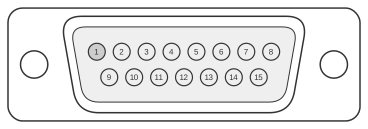 15 pin D-SUB male connector to the PC
The Atari-style DE-9 joystick interface, established with the Atari 2600 (1977) and carried forward on Atari 8-bit computers, the Commodore 64, and the Amiga, uses five active-low digital switches — Up, Down, Left, Right, and Fire — each connecting a signal pin to ground when actuated. The IBM PC Game Control Adapter, defined in the IBM PC Technical Reference (April 1983), uses a fundamentally different analogue interface: position is read by timing an RC circuit where a potentiometer of 0–100 kohm sets the time constant per axis via I/O address hex 201. Because these interfaces are electrically incompatible, a passive resistor network is insufficient; an active adapter circuit using transistors and diodes is required to translate each digital switch state into the appropriate resistance value seen by the PC game port.
Stick position to game-port resistance
The adapter directly connects the joystick fire button to the corresponding PC joystick button pin, since both use an active-low switch to ground. For the position axes, the circuit converts the four direction switch inputs from the DE-9 connector into X and Y resistance values presented to the PC game port. The PC game port timing equation (T = 24.2 µs + 0.011 × R µs) means that 0 kohm corresponds to full deflection in one direction, 50 kohm to centre, and 100 kohm to full deflection in the other. The nine positions of the Atari stick produce the following resistance pairs:
| Joystick position | X pot | Y pot |
|---|---|---|
| Up-left | 0 kΩ | 0 kΩ |
| Up | 50 kΩ | 0 kΩ |
| Up-right | 100 kΩ | 0 kΩ |
| Left | 0 kΩ | 50 kΩ |
| Centre | 50 kΩ | 50 kΩ |
| Right | 100 kΩ | 50 kΩ |
| Down-left | 0 kΩ | 100 kΩ |
| Down | 50 kΩ | 100 kΩ |
| Down-right | 100 kΩ | 100 kΩ |
These values match those produced by analogue PC joysticks and gamepads such as the Gravis Gamepad. The fire button on the DE-9 (pin 6) connects directly to Button 1 on the DA-15 PC connector; a second button (DE-9 pin 5 or pin 9, depending on the joystick model) connects to Button 2.
Getting more buttons to work
The use of extra buttons beyond the primary fire button is not standardised across Atari-compatible joysticks. If Button 2 does not respond, the joystick may route the extra button to pin 9 rather than pin 5 on the DE-9 connector. Move the wire from pin 5 to pin 9, or bridge pin 5 and pin 9 together so that either pin activates Button 2 regardless of which one the joystick uses.
Notes
- The IBM PC Technical Reference labels the four button signals on the DA-15 connector as Button 4, 5, 6, and 7 (reflecting data register bits 4–7 at I/O address hex 201). Peripheral documentation commonly renumbers these as Button 1, 2, 3, and 4; the physical wiring is unaffected.
- The DE-9 joystick direction and fire signals are active-low: the switch connects the signal pin to GND (pin 8) when actuated; the host provides a pull-up to +5 V so an open switch reads logic 1 and a closed switch reads logic 0.
- The PC game port supplies +5 V on DA-15 pins 1, 8, 9, and 15; ground on pins 4, 5, and 12. All four one-shots are triggered simultaneously by a write to I/O address hex 201.