
The Welch Allyn ScanTeam 8300-4 is a multi-function check reader, magnetic-stripe reader, and optional barcode scanner from the late 1990s. Its rear panel carries a single DB-15F (15-pin D-SUB female) host port that multiplexes several interface modes — RS-232, keyboard wedge, OCIA, and OCR — together with DC power input, over one connector. The 8300-4 variant has its own distinct pin assignments, differing from those of the 8300-1 and 8300-2 models. The device was manufactured by Welch Allyn, Inc. of Skaneateles Falls, NY, and was published in 1998.
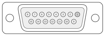 15 pin D-SUB female connector at the back of the 8300-4
| Pin | Name | Direction | Description |
|---|---|---|---|
| 1 | Logic Ground | - | |
| 2 | VCC (+5vdc) | - | For supplying +5 VDC to the scanner |
| 3 | RXD | IN | Receive data (RS-232 voltages) |
| 4 | CTS | IN | Clear to Send (RS-232 voltages) |
| 5 | KbdDataIn | IN | Keyboard wedge data (from a keyboard) |
| 6 | KbdClkIn | IN | Keyboard wedge clock (from a keyboard) |
| 7 | RDATA | OCIA | |
| 8 | Data ready | OCR, or 5B RX/TX | |
| 9 | Vin(+12vdc) | - | +12 VDC input, optional if +5 VDC is supplied |
| 10 | Bootstrap | IN | Short to ground to enable bootstrap mode |
| 11 | TXD | OUT | Transmit data (RS-232 voltages) |
| 12 | RTS | OUT | Request to Send (RS-232 voltages) |
| 13 | KbdDataOut | OUT | Keyboard data (to computer) |
| 14 | KbdClkOut | OUT | Keyboard clock (to computer) |
| 15 | 5B RX2/TX2 | 5B RX/TX |
Notes
The DB-15F connector on the rear panel combines four distinct host interface modes over a single 15-pin plug: RS-232 serial (pins 3, 4, 11, 12), keyboard wedge (pins 5, 6, 13, 14), OCIA (pins 7, 14), and OCR/5B (pin 8, pin 15). The active interface is selected by the host cable wired to the unit. The device is powered via pin 2 (+5 V DC) or pin 9 (+12 V DC) supplied by the host; it ships factory-configured for host-powered operation. Pin 10 (Bootstrap) must be shorted to Logic Ground (pin 1) to enter bootstrap/firmware-update mode. Pin 14 carries a dual function: keyboard wedge terminal clock output and D1 (OCIA). Pin 8 is bidirectional and dual-function: Data Ready (OCR) or 5B RX/TX. The 8300-4 variant pin assignments differ from those of the 8300-1 and 8300-2; consult the technical manual when substituting cables between variants.
Signals
- Logic Ground — signal and chassis ground reference
- VCC (+5vdc) — +5 V DC host-supplied power input
- RXD — RS-232 receive data (input to scanner)
- CTS — RS-232 Clear to Send (input to scanner)
- KbdDataIn — keyboard wedge data input (from keyboard)
- KbdClkIn — keyboard wedge clock input (from keyboard)
- RDATA — OCIA receive data
- Data ready — Data Ready signal for OCR mode; also used as 5B RX/TX in 5B interface mode
- Vin(+12vdc) — +12 V DC host-supplied power input; used when +5 V is not available
- Bootstrap — short to Logic Ground to enable firmware bootstrap mode
- TXD — RS-232 transmit data (output from scanner)
- RTS — RS-232 Request to Send (output from scanner)
- KbdDataOut — keyboard wedge data output (to computer)
- KbdClkOut — keyboard wedge terminal clock output (to computer); also D1 (OCIA)
- 5B RX2/TX2 — 5B RX/TX bidirectional signal