
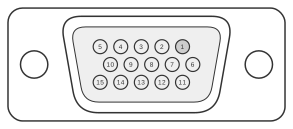
 15 pin highdensity D-SUB female connector at the cable
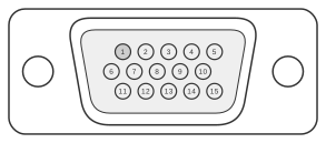 15 pin highdensity D-SUB male connector at the device
The Fargo Telecom Maestro 20 and Maestro 100 are dual-band GSM 900/1800 MHz GPRS modems manufactured by Fargo Services (HK) Ltd. and introduced in the early 2000s. Both models use a 15-pin high-density D-SUB (HD D-SUB 15) female connector on the device that carries RS-232 serial signals alongside analogue microphone and speaker audio, eliminating the need for a separate audio connector. The Maestro 20 supports GPRS Class 2, whilst the Maestro 100 supports GPRS Class 10 with an optional TCP/IP stack; both default to 9600 bps, 8N1 on the serial interface and implement AT commands per GSM 07.05 and GSM 07.07.
| Pin | Name | Direction | Description |
|---|---|---|---|
| 1 | DCD | OUT | Data Carrier Detect |
| 2 | TX | IN | Transmit Data |
| 3 | BOOT | IN | |
| 4 | MICROPHONE(+) | OUT | 0.5mA; 100mVpp |
| 5 | MICROPHONE(-) | OUT | |
| 6 | RX | OUT | Receive Data |
| 7 | DSR | OUT | Data Set Ready |
| 8 | DTR | IN | Data Terminal Ready |
| 9 | GND | - | Ground |
| 10 | SPEAKER(+) | 16mA; 32 Ohm | |
| 11 | CTS | OUT | Clear To Send |
| 12 | RTS | IN | Request To Send |
| 13 | RI | OUT | Ring Indicator |
| 14 | RESET | IN | |
| 15 | SPEAKER(-) |
Notes
The connector on the device is a 15-pin HD D-SUB female; the mating cable plug is therefore 15-pin HD D-SUB male. Direction labels (IN/OUT) are from the perspective of the host DTE equipment: signals marked IN flow into the modem, signals marked OUT flow from the modem to the DTE. Pin 3 (BOOT) is listed as an input in the OEM manual but is stated as not used in normal operation. Pin 14 (RESET) resets the modem when pulled low. The microphone input uses a 2 V DC bias supplied by the modem; the speaker output is rated for 32 Ω impedance. Power is supplied separately via a 4-pin Micro-Fit 3.0 connector (5–32 V DC), not through the HD D-SUB.
Signals
- DCD — Data Carrier Detect; asserted by the modem when a carrier is detected on the GSM network.
- TX — Transmit Data from the DTE to the modem (RS-232).
- BOOT — Boot control input; not used in normal operation.
- MICROPHONE(+) — Positive microphone input; modem supplies 2 V DC bias at 0.5 mA minimum (2 kΩ load), maximum input level 100 mVpp.
- MICROPHONE(-) — Negative (return) microphone input.
- RX — Receive Data from the modem to the DTE (RS-232).
- DSR — Data Set Ready; asserted by the modem to indicate it is powered and ready.
- DTR — Data Terminal Ready; asserted by the DTE to enable the modem.
- GND — Signal and audio ground.
- SPEAKER(+) — Positive speaker output; 16 mA typical, rated for 32 Ω impedance, 150 Ω/1 nF load.
- CTS — Clear To Send; asserted by the modem to indicate it can accept data.
- RTS — Request To Send; asserted by the DTE to request permission to transmit.
- RI — Ring Indicator; pulsed by the modem on an incoming call.
- RESET — Hardware reset input; pulling this line low resets the modem.
- SPEAKER(-) — Negative (return) speaker output.