
The Comcom Electronics JTAG header is an 8-pin proprietary board header implementing the IEEE 1149.1 Test Access Port (TAP) interface, used to connect in-circuit debuggers and programmers to FPGA and CPLD devices. The underlying TAP protocol, standardised in IEEE 1149.1-1990 and last revised in 2013, defines five signals — TCK, TMS, TDI, TDO, and the optional TRST reset — but leaves the physical connector format to the discretion of individual vendors. This 8-pin layout carries those signals alongside power and ground, enabling boundary-scan testing, device programming, and in-system debugging of Xilinx, Altera/Intel, and other FPGA and CPLD families.
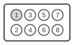
| Pin | Name | Direction | Description |
|---|---|---|---|
| 1 | TCK | OUT | Test Clock |
| 2 | GND | - | Ground |
| 3 | TDI | OUT | Test Data Input |
| 4 | GND | - | Ground |
| 5 | TDO | IN | Test Data Output |
| 6 | VCC | - | Power Supply |
| 7 | TMS | OUT | Test Mode Select |
| 8 | TRS | OUT | Test Reset |
Notes
The connector pitch and exact mating part are not publicly documented by Comcom Electronics; board designers should verify mechanical compatibility before use. The JTAG TAP state machine is a 16-state FSM clocked on the rising edge of TCK, with TMS transitions selecting the next state. For multi-device chains, TDO of one device connects to TDI of the next, with TCK and TMS shared across all devices. TCK should be pulled low (typically 1 kΩ) and TMS/TDI pulled high (1–10 kΩ) when the header is unpopulated.
Signals
- TCK — Test Clock; clocks the TAP state machine and all boundary-scan registers on its rising edge.
- GND — Ground reference for all signal levels on the header.
- TDI — Test Data In; serial data shifted into the device’s instruction and data registers on the TCK rising edge.
- TDO — Test Data Out; serial data shifted out of the selected register, valid on the TCK falling edge.
- VCC — Target power reference; supplies or senses the board logic voltage for the debug adapter.
- TMS — Test Mode Select; sampled on the TCK rising edge to control TAP state-machine transitions.
- TRS — Test Reset; active-low signal that asynchronously resets the TAP controller to the Test-Logic-Reset state (corresponds to optional TRST in IEEE 1149.1).