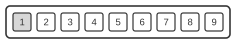
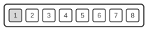
Pinout of the data/sync cable connector and display connector on the Nokia 3300 mobile phone.
Your support helps keep this website running. Please consider supporting this project. SPONSORDONATE
- Nicola Asuni
Updated:
This page documents the connector used by a third-party data and sync cable for the Nokia 3300 handset. The pin layout is specific to this model and its associated accessories. Only the pins employed by the cable are listed below.
Pin
Signal
1
Vpp
2
FBus Tx
3
MBus
4
FBus Rx
5
Gnd
6
Gnd (-)
7
BTemp (Temperature)
8
BSI (Battery Type / Capacity)
9
Vcc (+)
Display Connector
Pin
Signal
1
LCDRSTX - Reset (2,8V)
2
VOUT - DC/DC voltage converter output (0V)
3
Gnd (0V)
4
LCDCSX - Chip select input (2,8V)
5
LCDCDX - Control/display data flag input (2,8V)
6
SDA - Serial data input (0V)
7
SCLK - Serial clock input (0V)
8
VBB - Suply voltage (2,8V)
Notes
Pin numbers refer to the connector on the handset; pins not listed are unused by the cable.