Pinout of the internal connector and accessory jacks used by data, charging, and handsfree cables for the Nokia 3210 mobile phone.
Your support helps keep this website running. Please consider supporting this project. SPONSORDONATE
- Nicola Asuni
Updated:
Rear View of Nokia 3210 Cellular Phone
This page documents the connectors found on the Nokia 3210 handset as used by third-party data, charging, and handsfree cables. The connector layout is specific to this model and is not shared with other Nokia families. Only the pins used by the respective cables are listed below.
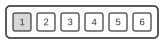
Pin
Signal
1
VPP
2
RX (FBUS)
3
DATA (MBUS)
4
GND - Ground
5
TX (FBUS)
6
BTEMP
Nokia 3210 Connector (keypad is up)
Pin
Signal
Description
1
+V
+3.7V DC - 355mA
2
?
?
3
GND
Ground
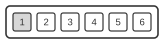
A Connector
A connector - 2 pins 3.5mm
Pin
Signal
Description
1
+V
+3.7V DC - 355mA
2
GND
Ground
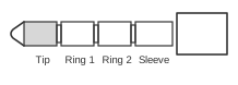
B Connector
B connector - 4 pins 3.5mm
Pin
Signal
Description
1
Mic IN
Microphone Input - 1KOhm or 1.5KOhm, 0Ohm when HANG UP button is pressed
2
Audio OUT
Audio Out
3
Mic GND
Microphone Ground
4
Audio GND
Audio Ground
Notes
Pin numbers refer to the connector on the handset; pins not listed are unused by the cable.

 Rear View of Nokia 3210 Cellular Phone
 Nokia 3210 Connector (keypad is up)
 A connector - 2 pins 3.5mm
 B connector - 4 pins 3.5mm