
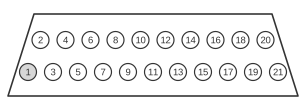
 21 pin SCART male connector
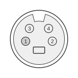 4 pin mini-DIN male connector
The SCART connector is a 21-pin interface standardised in Europe under CENELEC EN 50049-1 (electrical/signalling) and IEC 60807-9:1993 (mechanical), carrying composite video, stereo audio in/out, and — via an extension incorporated into EN 50049-1 in the late 1980s — S-Video (Y/C) luminance and chrominance. Composite video is 1.0 V peak-to-peak into 75 Ω, identical to the RCA composite standard; S-Video luminance Y rides on SCART pin 19 (output) and chrominance C on pin 15. An adapter to RCA and 4-pin mini-DIN breaks out these signals to the conventional consumer connectors used on VCRs, televisions, and set-top boxes throughout the analogue video era.
SCART S-Video Connection
| Output connector | Input connector |
|---|---|
| 1 | Audio right out |
| 3 | Audio left (or mono) out |
| 4 | Audio return |
| 15 | Chrominance out |
| 13 | Chrominance return |
| 8 | Video status out |
| 19 | Luminance out |
| 17 | Luminance return |
| 21 | Shield |
SCART Composite Video Connection
| Output connector | Input connector |
|---|---|
| 1 | Audio right out |
| 3 | Audio left (or mono) out |
| 4 | Audio return |
| 8 | Video status out |
| 19 | Composite video out |
| 17 | Composite video return |
| 21 | Shield |
Notes
Pin 8 (video status out) carries a control voltage that signals aspect ratio and signal type to the receiving device: approximately 0 V indicates no signal, 4.5–7 V indicates 4:3 content, and 9.5–12 V indicates 16:9 content. This voltage is not forwarded by a passive RCA or S-Video adapter.
Signals
- Audio right out — right-channel analogue audio output, nominal −10 dBV into high impedance; carried on SCART pin 1 and typically routed to a phono (RCA) socket
- Audio left (or mono) out — left-channel or mono analogue audio output; SCART pin 3
- Audio return — common ground for audio signals; SCART pin 4
- Chrominance out — S-Video colour subcarrier (C), 3.58 MHz (NTSC) or 4.43 MHz (PAL) into 75 Ω; SCART pin 15, maps to pin 3 of the 4-pin mini-DIN
- Chrominance return — ground for chrominance signal; SCART pin 13
- Video status out — aspect-ratio and signal-presence control voltage on SCART pin 8; not carried to RCA/S-Video
- Luminance out — S-Video luma (Y), 1.0 V peak-to-peak into 75 Ω; SCART pin 19, maps to pin 1 of the 4-pin mini-DIN
- Luminance return — ground for luminance signal; SCART pin 17
- Composite video out — CVBS signal, 1.0 V peak-to-peak (0.7 V picture + 0.3 V sync) into 75 Ω; SCART pin 19, routed to an RCA yellow socket
- Composite video return — ground for composite video signal; SCART pin 17
- Shield — connector shell/chassis ground; SCART pin 21