
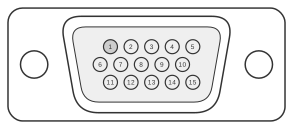
 15 pin highdensity D-SUB male connector
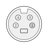 4 pin mini-DIN female connector
The Matrox G450 and G550 TV-output adapter connects to the secondary HD-15 (15-pin D-Sub analogue) connector on the graphics card and provides both composite video and S-Video (Y/C) output for connection to a television. Introduced around 2000–2001, the adapter was supported on the G450 Series, G550 Series, P Series, and Parhelia families. Both NTSC (North America, Japan) and PAL (Western Europe, China) television standards are supported. Pins 12 and 15 on the HD-15 connector are shorted together by the adapter, enabling the card to detect its presence. A separate optional SCART adapter was available for European users.
| Pin | Signal | Description |
|---|---|---|
| 1 | Composite Video | Composite video output |
| 2 | Y | S-Video luminance (Y) output |
| 3 | C | S-Video chrominance (C) output |
| 4 | NC | Not connected |
| 5 | GND | Ground |
| 6 | GND | Ground |
| 7 | GND | Ground |
| 8 | GND | Ground |
| 9 | - | Not used by adapter |
| 10 | GND | Ground |
| 11 | NC | Not connected |
| 12 | SENSE | Shorted to pin 15 for adapter detection |
| 13 | - | Not used by adapter |
| 14 | - | Not used by adapter |
| 15 | SENSE | Shorted to pin 12 for adapter detection |
Notes
The adapter plugs into the secondary HD-15 connector on the card; the primary HD-15 connector remains available for a VGA monitor. TV output is not supported when a digital dual-monitor cable is in use, nor in full-screen DOS display modes.
Pins 12 and 15 are shorted together inside the adapter housing; the card uses this connection to detect that the TV-output adapter is attached rather than a standard VGA monitor.
The S-Video (mini-DIN 4) connector carries Y on pin 2 and C on pin 3 of the HD-15 source, conforming to the standard S-Video Y/C signal separation. Composite video is available simultaneously on pin 1.
Signals
- Composite Video — standard composite video output signal; supports NTSC and PAL
- Y — S-Video luminance channel
- C — S-Video chrominance channel
- GND — signal ground; multiple pins (5, 6, 7, 8, 10) connected to ground
- SENSE — adapter-detection pins; pins 12 and 15 are shorted by the adapter
- NC — not connected (pins 4 and 11)