
 9 pin D-SUB male connector to the videocard
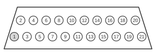 21 pin SCART male connector to the TV
Some ATI Radeon graphics cards from the late 1990s and early 2000s were capable of generating analogue RGB signals directly on the VGA (HD-15) output, making it possible to route video to a television via a passive cable rather than a scan converter. SCART (standardised as CENELEC EN 50049-1 / IEC 933-1) is a 21-pin connector introduced in 1977 that carries RGB, composite, S-Video, stereo audio, and switching signals. This cable maps the RGB and composite-sync lines from the 9-pin D-Sub connector on the graphics card to the corresponding RGB input pins on the SCART socket, along with audio from a sound card. The connection requires an RGB-capable SCART socket on the television.
| Pin | Signal | Description |
|---|---|---|
| 1 | 15 | red |
| 2 | 11 | green |
| 3 | 7 | blue |
| 6 | 13 | Red return |
| 7 | 9 | Green return |
| 8 | 5 | Blue return |
| 9 | 8 | pins 8 and 16 are connected via R=75Ohm |
| 10 | 17 | Composite sync return |
| 13 | 20 | Composite sync |
| chassis | 21 | ground |
| Audio OUT (from soundcard) | ||
| jack/1 | 6 | |
| jack/2 | 2 | |
| jack/3 | 4 |
Notes
SCART sockets are not uniformly wired across television sets. The original SCART socket accepted either composite or RGB video input. Later sockets were revised to accept either S-Video or composite video instead of RGB. This wiring scheme requires an RGB-capable SCART socket. Some televisions provide three SCART sockets: the first (often black) accepts composite and RGB, whilst the remaining sockets (often orange) accept S-Video and composite only. Older or lower-end sets with a single SCART socket are generally wired for composite and RGB.
SCART pin 8 is the aspect-ratio and mode-switching pin; connecting it to pin 16 through a 75 Ω resistor signals RGB mode to the television and selects the correct input automatically on sets that support this function.
Audio connections use a stereo jack from the sound card: jack tip to SCART pin 6 (right audio in), jack ring to SCART pin 2 (right audio in return), and jack sleeve to SCART pin 4 (left audio in).