
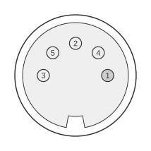
 5 PIN DIN 180° (DIN41524) MALE to the 1st peripheral.)
5 PIN DIN 180° (DIN41524) MALE to the 2nd peripheral.
MIDI (Musical Instrument Digital Interface) is a serial communication standard introduced in 1983 and jointly governed by the MIDI Manufacturers Association (MMA) and the Japanese AMEI organisation, with the definitive document being the MIDI 1.0 Detailed Specification. The physical connector is a 5-pin 180° DIN (DIN 41524), with female panel-mount receptacles on devices and male plugs on cables; of the five pins, only three carry signals: pin 2 (cable shield/ground), pin 4 (current source, +5 V through a 220 Ω resistor), and pin 5 (current sink/signal). The electrical interface is an optically isolated 5 mA current loop running at 31.25 kbaud ±1%, asynchronous, using 10-bit frames (1 start bit, 8 data bits, 1 stop bit); the MIDI IN receiver must opto-isolate the signal to prevent ground loops. Maximum cable length is 50 ft (15 m) using shielded twisted pair, with the shield connected to pin 2 at both ends and left ungrounded at the MIDI IN end. A 2014 update (CA-033) extended the specification to support 3.3 V signalling and introduced optional ferrite-bead RF filters on pins 4 and 5; pin assignments were unchanged.
| 1st | 2nd | |
|---|---|---|
| Shield | 2 | 2 |
| Current Source | 4 | 4 |
| Current Sink | 5 | 5 |
Notes
Pins 1 and 3 are defined as unused and must be left unconnected in both transmitter and receiver. Pin 2 carries the cable shield/ground; in the MIDI OUT circuit it is connected at both ends of the cable, but it must NOT be grounded at the MIDI IN receiver — doing so creates a ground loop. The maximum cable length is 50 ft (15 m) using shielded twisted pair. Acceptable opto-isolators for the MIDI IN receiver circuit are the Sharp PC-900 and the HP 6N138; all resistors should be 5% tolerance. The standard requires connectors to be labelled MIDI IN, MIDI OUT, and MIDI THRU.
Signals
- Shield (Pin 2) — cable shield/ground, connected at both cable ends; must not be grounded at MIDI IN
- Current Source (Pin 4) — current-loop source, +5 V (or 3.3 V per CA-033) through a 220 Ω resistor on the MIDI OUT side
- Current Sink (Pin 5) — current-loop sink; carries the MIDI serial data stream (logical 0 = current ON)