
A soundcard-to-soundcard MIDI patch uses a standard 5-pin DIN (DIN 41524 / IEC 60130-9) cable to connect the MIDI OUT port of one device to the MIDI IN port of another. The MIDI 1.0 Detailed Specification, first published in 1983 and maintained by the MIDI Manufacturers Association (MMA) and AMEI, governs both endpoints; the 2014 CA-033 update extended the standard to support 3.3 V signalling whilst leaving the connector and pin assignments unchanged. No proprietary adapter electronics are required: the transmitting device drives a 5 mA current loop through pin 4 (+5 V via 220 Ω) and pin 5 (signal), and the receiving device opto-isolates its MIDI IN to prevent ground loops.
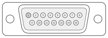 15 PIN D-SUB MALE
15 PIN D-SUB MALE
| Pin 1st | Name | Pin 2nd | Name |
|---|---|---|---|
| 4, 5 | GND | 4, 5 | GND |
| 12 | MIDI TXD | 15 | MIDI RXD |
| 15 | MIDI RXD | 12 | MIDI TXD |
Notes
The cable must be shielded twisted pair with a maximum length of 50 ft (15 m). The shield connects to pin 2 of the DIN-5 connector at both ends; the MIDI IN end must not ground pin 2 to chassis, as doing so creates a noise-inducing ground loop. Pins 1 and 3 of the DIN-5 are defined as unused and must remain unconnected.
The data rate is 31.25 kbaud ±1%, asynchronous, using 10-bit frames (1 start bit, 8 data bits, 1 stop bit); each byte takes 320 µs to transmit. Logical 0 is represented by current ON (approximately 5 mA).
Signals
- GND — cable shield / ground reference; connected to DIN-5 pin 2 at both ends of the cable
- MIDI TXD — MIDI transmit data out from the soundcard; drives the current loop via DIN-5 pin 4 (+5 V through 220 Ω) and pin 5 (signal)
- MIDI RXD — MIDI receive data into the soundcard; opto-isolated at the MIDI IN jack to prevent ground loops