
The Attachment Unit Interface (AUI) is the IEEE 802.3 (Clause 7) 15-pin DA-15 interface between an Ethernet station’s MAC/PLS and its Medium Attachment Unit (MAU, or transceiver), standardised since IEEE 802.3-1985. It carries four differential-pair circuits — Data Out (DO), Data In (DI), Control In (CI, collision detect), and Control Out (CO) — plus power rails (+12 V VP, VC return), per-circuit shields, and a protective ground shell; the DA-15 connector uses a sliding-clip latch rather than thumbscrews. The AUI drop cable has a characteristic impedance of 78 Ω and a maximum length of 50 m; on 10BASE-2 (thinnet) installations the drop cable must not exceed 1.33 m. Many routers and network interface cards, including certain Cisco models, expose an AUI port to allow connection to an external transceiver for conversion to twisted-pair, coaxial, or fibre media.
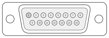 Ethernet (AUI) Port Pinout (DB-15)
| Pin1 | Ethernet Circuit | Signal |
|---|---|---|
| 3 | DO-A | Data Out Circuit A |
| 10 | DO-B | Data Out Circuit B |
| 11 | DO-S | Data Out Circuit Shield |
| 5 | DI-A | Data In Circuit A |
| 12 | DI-B | Data In Circuit B |
| 4 | DI-S | Data In Circuit Shield |
| 2 | CI-A | Control In Circuit A |
| 9 | CI-B | Control In Circuit B |
| 1 | CI-S | Control In Circuit Shield |
| 6 | VC | Voltage Common |
| 13 | VP | Voltage Plus |
| 14 | VS | Voltage Shield (L25 and M25) |
| Shell | PG | Protective Ground |
Notes
- (1) Any pin not referenced is not connected.
- The CO (Control Out) circuit — AUI pins 7 (CO-A), 8 (CO-S), and 15 (CO-B) — is not present in this table because DTE-side implementations do not implement CO; those pins are legally absent on the DTE connector.
- The DTE-side connector is female (DA-15F); the MAU-side connector is male (DA-15M). The sliding-clip latch distinguishes the AUI DA-15 from the DB-15 used on other interfaces.
- VP (pin 13) supplies +12 V DC at up to 500 mA to power the MAU. Not all host devices supply +12 V internally; verify the host’s power budget before connecting a transceiver.
- Cable characteristic impedance: 78 Ω; maximum drop-cable length: 50 m (10BASE-5) or 1.33 m (10BASE-2).
Signals
- DO-A / DO-B — Data Out differential pair (circuit A non-inverting, circuit B inverting); carries transmit data from DTE to MAU.
- DO-S — Data Out circuit shield; individually screened for the DO pair.
- DI-A / DI-B — Data In differential pair; carries receive data from MAU to DTE.
- DI-S — Data In circuit shield.
- CI-A / CI-B — Control In differential pair; carries collision-presence signal from MAU to DTE.
- CI-S — Control In circuit shield.
- VC — Voltage Common; power return for the VP supply rail.
- VP — Voltage Plus; +12 V DC supply from DTE to MAU (up to 500 mA per IEEE 802.3).
- VS — Voltage Shield; shield for the power conductors (L25 and M25 cable variant).
- PG — Protective Ground; connected to the DA-15 shell and equipment chassis.