
A straight-through patch cable connects an MDI end-station (PC or NIC) to an MDI-X port on a hub or switch using an 8P8C modular plug, commonly called RJ45. The wiring conventions are defined by ANSI/TIA-568 (current edition TIA-568-2020) and the electrical signalling by IEEE 802.3, which covers 10BASE-T (Clause 14, originally 802.3i-1990), 100BASE-TX (Clause 25, 802.3u-1995), and 1000BASE-T (Clause 40, 802.3ab-1999). For 10BASE-T and 100BASE-TX, only two pairs are active: pins 1–2 transmit and pins 3–6 receive at the MDI end. For 1000BASE-T all four pairs carry data bidirectionally using PAM-5 encoding, so the BI_DA through BI_DD signal names from IEEE 802.3 Clause 40 apply across all speeds. Where a direct MDI-to-MDI or MDI-X-to-MDI-X connection is required, a crossover cable or auto-MDI/MDI-X port should be used instead.
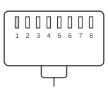
RJ45 MALE CONNECTOR To network interface card)
RJ45 MALE CONNECTOR To hub
TIA/EIA 568A
| Pin | Signal | TIA/EIA 568A | Pin | Signal | TIA/EIA 568A | |
|---|---|---|---|---|---|---|
| 1 | BI_DA+ (TX+) |  white/green
 | 1 | BI_DA+ (TX+) |
white/green | |
| 2 | BI_DA- (TX-) |  green
green | 2 | BI_DA- (TX-) |
green | |
| 3 | BI_DB+ (RX+) |  white/orange
 | 3 | BI_DB+ (RX+) |
white/orange | |
| 4 | BI_DC+ |  blue
blue | 4 | BI_DC+ |
blue | |
| 5 | BI_DC- |  white/blue
 | 5 | BI_DC- |
white/blue | |
| 6 | BI_DB- (RX-) |  orange
 | 6 | BI_DB- (RX-) |
orange | |
| 7 | BI_DD+ |  white/brown
 | 7 | BI_DD+ |
white/brown | |
| 8 | BI_DD- |  brown
brown | 8 | BI_DD- |
brown |
TIA/EIA 568B
| Pin | Signal | TIA/EIA 568B | Pin | Signal | TIA/EIA 568B | |
|---|---|---|---|---|---|---|
| 1 | BI_DA+ (TX+) |
white/orange | 1 | BI_DA+ (TX+) |
white/orange | |
| 2 | BI_DA- (TX-) |
orange | 2 | BI_DA- (TX-) |
orange | |
| 3 | BI_DB+ (RX+) |
white/green | 3 | BI_DB+ (RX+) |
white/green | |
| 4 | BI_DC+ |
blue | 4 | BI_DC+ |
blue | |
| 5 | BI_DC- |
white/blue | 5 | BI_DC- |
white/blue | |
| 6 | BI_DB- (RX-) |
green | 6 | BI_DB- (RX-) |
green | |
| 7 | BI_DD+ |
white/brown | 7 | BI_DD+ |
white/brown | |
| 8 | BI_DD- |
brown | 8 | BI_DD- |
brown |
Notes
- Each twisted pair must be kept intact: TX+ and TX- must occupy the same pair, and RX+ and RX- must occupy another. Splitting a pair across non-paired positions degrades noise rejection and increases crosstalk.
- The + conductor of each pair is traditionally termed the “tip” and the − conductor the “ring”, terminology inherited from early telephone cabling.
- T568A and T568B differ only in the assignment of the orange and green pairs (pins 1–2 and 3–6 are swapped between the two schemes); electrical performance is identical. T568A is the preferred scheme under ANSI/TIA-568 and is required for US Federal Government installations; T568B matches the earlier AT&T 258A colour code and remains widely used in commercial premises wiring. Both ends of a straight-through cable must use the same colour code.
- For 10BASE-T and 100BASE-TX the pairs on pins 4–5 and 7–8 carry no signal; for 1000BASE-T all four pairs are active (BI_DA through BI_DD) and each pair operates bidirectionally.
- Auto-MDI/MDI-X, standardised in IEEE 802.3 Clause 40 and widely implemented since the mid-2000s, allows a switch or NIC port to detect the cable type automatically and reconfigure itself accordingly, eliminating the need to select between straight-through and crossover cables in most modern installations.