
A 10BASE-T crossover cable connects two MDI end-stations (such as PCs or NICs) directly, without an intervening hub or switch, by swapping the transmit pair (pins 1–2) on one end with the receive pair (pins 3–6) on the other. This two-pair crossover is also electrically compatible with 100BASE-TX (Fast Ethernet). The MDI/MDI-X distinction and the required crossover were formalised in IEEE 802.3i-1990 (Clause 14 of the current consolidated standard, IEEE 802.3-2022). For Gigabit Ethernet (1000BASE-T), which uses all four pairs bidirectionally, see the Ethernet 10/100/1000 base-T4 Crossover Cable page.
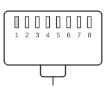
RJ45 MALE CONNECTOR To network interface card 1
RJ45 MALE CONNECTOR To network interface card 2
| Pin | Signal | Color | Pin | Signal | Color | |
|---|---|---|---|---|---|---|
| 1 | TX+ |  white/green
 | 3 | RX+ |  white/orange
 | |
| 2 | TX- |  green
green | 6 | RX- |  orange
 | |
| 3 | RX+ |
white/orange | 1 | TX+ |
white/green | |
| 4 | n/c | 4 | n/c | |||
| 5 | n/c | 5 | n/c | |||
| 6 | RX- |
orange | 2 | TX- |
green | |
| 7 | n/c | 7 | n/c | |||
| 8 | n/c | 8 | n/c |
Notes
- Each twisted pair must be kept intact: TX+ and TX− must share a pair, and RX+ and RX− must share a separate pair, as shown in the table above.
- The + side of each pair is traditionally called the “tip” and the − side the “ring”, terms inherited from telephone wiring conventions.
- The colour codes shown (white/green–green for the TX pair, white/orange–orange for the RX pair) follow the T568A scheme defined in ANSI/TIA-568. T568B swaps those two pairs, placing white/orange–orange on pins 1–2 and white/green–green on pins 3–6; a crossover cable can also be made by wiring T568A on one end and T568B on the other. Either combination achieves the required pair swap; the choice of colour code does not affect electrical performance.
- Pins 4–5 and 7–8 are unused (not connected) in both 10BASE-T and 100BASE-TX; only the two active pairs (pins 1–2 and 3–6) need to be crossed.
- The connector is an 8P8C modular plug, commonly referred to as RJ45 in networking contexts.