
A Centronics-to-LapLink adapter re-maps the pins of a standard parallel printer cable — DB-25 male at the computer end, 36-pin Centronics female at the printer end — so that it functions as a LapLink or MS-DOS INTERLNK cross-transfer cable. The underlying technique exploits the IBM PC parallel port design, which exposes five unidirectional data outputs (pins 2–6 on DB-25) and five unidirectional status inputs (pins 10–13, 15 on DB-25); crossing these between two machines creates a half-duplex 5-bit-wide data path without requiring a bidirectional parallel port. The critical mapping difference from a straight-through printer cable is that DB-25 pin 15 (/ERROR) corresponds to Centronics pin 32 (/FAULT) — not Centronics pin 15, which is not connected in the standard interface. The parallel port operates at TTL voltage levels (0–5 V), and the LapLink/INTERLNK signalling predates the IEEE 1284-1994 standard that later formalised the PC parallel interface.
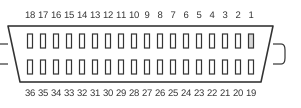 36 PIN CENTRONICS FEMALE to the Printer cable
 25 PIN D-SUB MALE to the Computer
| Name | 36-Cen | 25-DSub | Name |
|---|---|---|---|
| Data Bit 0 | 2 | 15 | Error |
| Data Bit 1 | 3 | 13 | Select |
| Data Bit 2 | 4 | 12 | Paper Out |
| Data Bit 3 | 5 | 10 | Acknowledge |
| Data Bit 4 | 6 | 11 | Busy |
| Acknowledge | 10 | 5 | Data Bit 3 |
| Busy | 11 | 6 | Data Bit 4 |
| Paper Out | 12 | 4 | Data Bit 2 |
| Select | 13 | 3 | Data Bit 1 |
| Error | 32 | 2 | Data Bit 0 |
| Reset | 16 | 16 | Reset |
| Select | 17 | 17 | Select |
| Signal Ground | 19-30+33 | 18-25 | Signal Ground |
Notes
- The Centronics connector is the 36-pin Amphenol-style plug used on the printer end of a standard parallel cable; the DB-25 end connects to the computer’s parallel (LPT) port.
- The essential cross-wiring is: Centronics 2–6 (data outputs) connect to DB-25 15, 13, 12, 10, 11 (status inputs), and vice versa; ground pins are common.
- Centronics pin 32 (/FAULT) carries the /ERROR signal that corresponds to DB-25 pin 15; Centronics pin 15 is not connected in the standard interface and must not be used instead.
- Pins 16 and 17 are connected straight-through (Reset/Init and SelectIn); these are included for compatibility with the commercial LapLink cable. The minimal 11-wire MS-DOS INTERLNK cable does not require these pins.
- Ground spans Centronics pins 19–30 and 33, which map to DB-25 pins 18–25; all carry signal ground at 0 V (TTL reference).
- All signals are TTL-compatible: logic HIGH ≥ 2.4 V, logic LOW ≤ 0.8 V; rise and fall times should be less than 0.2 µs per the IBM parallel port specification.
Signals
- Data Bit 0–4 — five unidirectional data output lines (DB-25 pins 2–6 / Centronics pins 2–6); cross-connected to the status inputs on the far end to carry one nibble per transfer cycle.
- Error — status input, active Low (DB-25 pin 15 / Centronics pin 32, /FAULT); receives Data Bit 0 from the remote port.
- Select — status input, active High (DB-25 pin 13 / Centronics pin 13); receives Data Bit 1 from the remote port.
- Paper Out — status input, active High (DB-25 pin 12 / Centronics pin 12); receives Data Bit 2 from the remote port.
- Acknowledge — status input, active Low (DB-25 pin 10 / Centronics pin 10); receives Data Bit 3 from the remote port.
- Busy — status input, active High (DB-25 pin 11 / Centronics pin 11); receives Data Bit 4 from the remote port.
- Reset — control line (DB-25 pin 16 / Centronics pin 16); connected straight-through; corresponds to the Init signal on the IBM parallel port.
- Select (control) — control line (DB-25 pin 17 / Centronics pin 17); connected straight-through; corresponds to SelectIn on the IBM parallel port.
- Signal Ground — reference ground; Centronics pins 19–30 and 33 connected to DB-25 pins 18–25.