
SCSI (Small Computer System Interface) is a parallel bus interface standard developed from the SASI (Shugart Associates System Interface) created in 1979 by Larry Boucher at Shugart Associates; Shugart and NCR jointly submitted a proposal to ANSI in 1981, and the standard was ratified as ANSI X3.131-1986 in 1986. SCSI-2 (INCITS 131-1994) introduced Fast SCSI at 10 MB/s and the Wide option using a 68-pin connector at up to 20 MB/s; the subsequent SCSI-3 family, defined by SPI-1 through SPI-5 and published by INCITS/T10, extended transfer rates to 320 MB/s with Ultra320. The interface was widely used for hard drives, tape devices, optical drives, and scanners in workstations and servers requiring high throughput and multi-device daisy-chain connectivity.
History
SCSI derives from the SASI interface devised by Shugart Associates. During the ANSI ratification process, the committee drew on elements of both SASI and IPI, renaming the result SCSI to avoid branding a standard after a single company. The standard was ratified as ANSI X3.131-1986 (SCSI-1) in 1986. Subsequent revisions — SCSI-2 (ANSI X3.131-1994) and the layered SCSI-3 family — tightened interoperability requirements and extended bus speeds, bus widths, and signalling options. The INCITS/T10 Technical Committee (formerly ANSI T10, renamed INCITS/SCSI in January 2022) remains the authoritative issuing body for all SCSI parallel interface standards.
Usage
SCSI connects peripherals — hard drives, tape devices, CD-ROMs, DVD drives, scanners, and printers — to a host adapter on a shared daisy-chain bus. The interface is particularly suited to server and workstation environments where multiple high-performance devices must share a single bus. Narrow SCSI (8-bit, 50-pin) supports up to eight devices per chain; Wide SCSI (16-bit, 68-pin) supports up to sixteen devices, providing greater throughput for demanding storage configurations.
SCSI Hard Drives
The standard internal cable for narrow SCSI is a 50-conductor flat ribbon cable, with all odd-numbered conductors grounded. Conductors 25 and 26 carry Terminator Power (TERMPWR) and must not be shorted; cable reversals risk shorting pin 26 to ground and damaging the drive or host adapter. The bus operates as a daisy-chain: each device with two connectors passes signals straight through, and the chain is terminated at both physical ends. The differential SCSI variant uses balanced twisted-pair wiring and is suited to high-end workstations where extended cable lengths are required.
Apple SCSI
Unlike the PC industry, Apple standardised on SCSI as its primary drive interface and adopted a non-standard DB-25 connector for external connections. Apple did not implement the complete ANSI specification; peripherals must be certified for Apple’s SCSI bus. The ANSI standard specifies a 50-pin Centronics-style A-cable connector (two parallel rows of 25 pins) as the normative external connector, providing additional ground conductors for improved signal isolation compared to a 25-pin D-shell.
Hardware
The basic narrow SCSI bus supports up to seven devices plus one host adapter, using three address lines to provide eight addresses (IDs 0–7). ID 7 is conventionally reserved for the host adapter, which holds the highest arbitration priority; ID 0 carries the lowest priority. Wide SCSI extends addressing to 16 devices (IDs 0–15). Each device’s SCSI ID is set via DIP switches or jumpers; no two devices may share the same ID on a given chain. Some devices have a fixed SCSI ID that cannot be changed; such fixed IDs must be verified against all other devices on the chain before installation.
Single-Ended or Differential
SCSI defines three mutually exclusive electrical signalling variants. Single-Ended (SE) uses TTL-compatible, active-low signals with a common ground return path; maximum bus length is 6 metres. High-Voltage Differential (HVD) uses RS-485 balanced pairs, one per signal, providing immunity to electrical interference and extending maximum cable length to 25 metres; HVD requires additional drivers and receivers and is correspondingly more expensive. Low Voltage Differential (LVD), introduced in SPI-3/Ultra2, uses lower-voltage balanced pairs integrated into drive controllers; LVD devices can auto-detect bus type via the DiffSens circuit and fall back to single-ended mode if non-LVD devices are present (multi-mode operation). LVD is NOT compatible with HVD — mixing them risks hardware damage. SE and HVD cannot be mixed on the same bus.
With LVD and a 16-device bus, maximum cable length is 12 metres; with fewer devices the limit extends to 25 metres. Minimum inter-device spacing is 30 cm (12 in).
Cabling
Internal devices use a 50-pin dual-inline connector on a flat ribbon cable; external devices use shielded cable with Centronics-style 50-pin connectors. The 50-pin A-cable is the original SCSI connector in both low-density Centronics and high-density (HD50) variants. Each external device carries two connectors wired pin-for-pin to support daisy-chaining; a terminator or the next device connects to the second port.
SCSI-2 defined a B-cable for 32-bit Wide SCSI, but manufacturers did not adopt it. Instead, the 68-pin P-cable — a high-density micro-D (HD68) connector in two rows of 34 pins — became the de facto standard for Wide SCSI (16-bit). The B-cable has since been abandoned. Some devices also support the SCA-2 80-pin single connector, which integrates power and control lines for hot-plug rack installations.
The Apple DB-25 external connector is not an ANSI-standardised variant; it uses SCSI-2 protocol at SCSI-1 speeds and accommodates only single-ended signalling due to insufficient pin count.
SCSI Termination
Termination is required at both physical ends of the SCSI bus. The host adapter and the device at the far end of the chain must each carry termination; all intermediate devices must have their terminators removed or disabled. If the host adapter is positioned in the middle of the chain, its terminators must be disabled and terminators placed at both physical ends instead. Terminators must be located within 10 cm (4 in) of each bus end. Improper termination causes signal reflections, resulting in missing peripherals, intermittent operation, or data loss.
The following ARE acceptable:
A SCSI bus must be terminated at, and only at, its two physical ends. A device in the middle of the chain leaves its terminator disabled (or removed); the two devices at the ends are terminated. When a host adapter sits at one end, its on-board terminator provides that end; the far device provides the other. Adapters placed in the middle of a bus that extends in both directions must have their termination disabled.
Three termination styles are used:
- Passive — 220 Ω to TERMPWR and 330 Ω to ground on each signal. Adequate for short, slow single-ended buses.
- Active — a 2.85 V regulator drives each signal through a single 110 Ω resistor, giving a stiffer reference for faster single-ended buses.
- Forced-perfect / differential — used on LVD/HVD buses; the terminator clamps each line to the regulated reference for the longest, fastest buses.
Figure 4: Differential termination
Forced Perfect Termination
Another method used for termination is FPT (Forced Perfect Termination). This method uses diode clamps to eliminate over and undershoot. Instead of clamping to +5 and GND they clamp to the output of two regulated voltages. This allows the clamping diodes to turn on earlier and is therefore better at eliminating overshoot and undershoot. Although this method would probably very good, it is not widely used.
Termination Power
Termination power is usually supplied by the host adapter, but any device is allowed to provide this power. To make sure that if another device on the chain is giving power to the TERMPWR signal line, they usually supply the power through diodes to prevent termination power from other devices from flowing back into the device. They usually also provide for a current limiting device so not to overload the signals and risking damage to devices connected on the bus.
SCSI Connectors
SCSI-1
 50-pin low-density (SCSI-1, Centronix, A-Cable)
 Apple DB-25 C
SCSI-2
SCSI-2 (Fast SCSI, Fast Narrow)
50-pin low-density (SCSI-1, Centronix, A-Cable)
 50-pin high-density (SCSI-2)
Fast Wide SCSI (Wide SCSI)
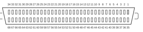 68-pin
SCSI-3
50-pin low-density (SCSI-1, Centronix, A-Cable)
50-pin high-density (SCSI-2)
68-pin
Ultra SCSI (SCSI-3, Fast-20, Ultra Narrow)
Wide Ultra SCSI (Fast Wide 20)
Ultra2 SCSI
Wide Ultra2 SCSI
Ultra3 SCSI
Wide Ultra3 SCSI
- A: Including Host Adapter
- B: Per channel
- C: The Apple DB-25 is not an official ANSI standard. It uses SCSI-2 protocol at SCSI-1 speeds.
- D: Differential allows for cable lengths of up to 25 metres.
- E: The DB-9 Fibre Channel connector is the industry standard, but only the four outer pins are live.
- LVD: Low Voltage Differential allows for cable lengths of up to 12 metres (25 metres with fewer devices).
- F: Standard systems carry 2 channels.
References
- INCITS/T10 Technical Committee — How to Get T10 Standards and other Publications
- SCSI Standards Architecture (T10/INCITS)
- Seagate Knowledge Base — SCSI Revision Levels
- Seagate Knowledge Base — Ultra3 SCSI Low Voltage Differential (LVD) Drives
- Small Computer System Interface – 2 (SCSI-2), Working Draft X3T9.2/375D rev 10l, ANSI X3.131-199x, dated 7 Sep 1993 (via Internet Archive)