
The ST506/ST412 interface is a hard disk drive standard introduced by Seagate Technology in the early 1980s — the ST506 in 1980 and the ST412 in 1981 — and used widely in IBM-compatible PCs through the mid-1980s. It employs two separate cables per installation: a single 34-pin control cable shared by all drives on the bus, and an individual 20-pin data cable connecting each drive directly to the controller. Drive selection is performed by hardware shunt configuration on each drive’s printed circuit board (IC position 6B/6E), not by any cable wiring crossover. The data lines carry MFM-encoded read and write signals as differential pairs conforming to EIA RS-422.
Control cable
 34 PIN IDC FEMALE to the Controller
34 PIN IDC FEMALE to the Drive 2
34 PIN IDC FEMALE to the Drive 1
| Controller | Drive 1 | Drive 2 | |
|---|---|---|---|
| Wire 1-24 | 1-9 | 1-9 | 1-9 |
| Wire 25 | 25 | 29 | 25 |
| Wire 26 | 26 | 28 | 26 |
| Wire 27 | 27 | 27 | 27 |
| Wire 28 | 28 | 26 | 28 |
| Wire 29 | 29 | 25 | 29 |
| Wire 30-34 | 30-34 | 30-34 | 30-34 |
Data cable
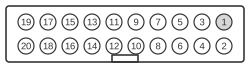 20 PIN IDC FEMALE to the Controller
20 PIN IDC FEMALE to the Drive
| Controller | Drive | |
|---|---|---|
| Wire 1-20 | 1-20 | 1-20 |
Signals — Control connector (34-pin)
All odd-numbered pins are ground. The connector is a PCB edge card type; mating connectors are AMP 88373-3 or Molex 15-35-1341. A key slot sits between pins 4 and 6.
- Pin 2 — Reduced Write Current — active-low input; instructs the drive to reduce write current for inner tracks
- Pin 4 — Head Select 2² — head address bit 2 (most significant); reserved on ST506
- Pin 6 — Write Gate — active-low input; enables write circuitry
- Pin 8 — Seek Complete — active-low output; asserted when the head has settled on the target track
- Pin 10 — Track 0 — active-low output; asserted when the head is positioned over track 0
- Pin 12 — Write Fault — active-low output; indicates a write fault condition
- Pin 14 — Head Select 2⁰ — head address bit 0 (least significant)
- Pin 16 — (ground)
- Pin 18 — Head Select 2¹ — head address bit 1
- Pin 20 — Index — active-low output; one pulse per disk revolution marking sector 0
- Pin 22 — Ready — active-low output; asserted when the drive is ready for a command
- Pin 24 — Step — active-low input; each falling edge advances the head one track in the direction set by Direction In
- Pin 26 — Drive Select 1 — active-low input; selects this drive when asserted; activated by on-board shunt configuration
- Pin 28 — Drive Select 2 — active-low input; selects this drive when asserted
- Pin 30 — Drive Select 3 — active-low input; selects this drive when asserted
- Pin 32 — Drive Select 4 — active-low input; selects this drive when asserted
- Pin 34 — Direction In — active-low input; determines step direction (low = towards spindle/inner tracks)
Control line electrical levels: True (asserted) = 0.0–0.4 V at −48 mA maximum; False = 2.5–5.25 V at +250 µA (open-collector outputs).
Signals — Data connector (20-pin)
The connector is a PCB edge card type; mating connectors are AMP 88373-6 or Molex 15-35-1201. Ground at pins 11, 15, and 19 (ST412) or pins 11, 15, 20 (ST506).
- Pin 2 — Drive Selected — active-low output; asserted when this drive is selected
- Pin 13 — +MFM Write Data — positive leg of differential MFM write data pair
- Pin 14 — −MFM Write Data — negative leg of differential MFM write data pair
- Pin 17 — +MFM Read Data — positive leg of differential MFM read data pair
- Pin 18 — −MFM Read Data — negative leg of differential MFM read data pair
Data lines are differential per EIA RS-422; characteristic impedance 105 ohms. Recommended driver/receiver pair: AMD 26LS31 / 26LS32. Maximum cable length 20 feet (flat ribbon or twisted pair).
Notes
- The control cable is a straight daisy-chain with no crossover wiring. Drive selection is set by cutting hardware shunts at IC position 6B (ST506) or 6E (ST412) on each drive’s PCB; the same control cable runs unmodified from controller through all drives.
- Termination on the control bus: a 220/330 ohm resistor pack must be fitted on the last drive in the chain.
- Each drive requires its own dedicated 20-pin data cable running directly to the controller; the data cable is point-to-point and straight (no twist or crossover).
- Write precompensation of ±12 ns applies to tracks 128 and above on ST412 drives (tracks 128–305 per ST412 manual; tracks 128–152 per ST506 manual).
- DC power is supplied via a 4-pin AMP Mate-N-Lok connector (350211-1): +12 V ±5% and +5 V ±5%.
References
- ST506 Product Manual (36036-001, July 1983) — Seagate Technology
- ST406/ST412/ST419 Product Manual (January 1984) — Seagate Technology