
The Nintendo Wii AV Multi Out is a proprietary 16-pin connector on the rear of the Wii console (model RVL-001, 2006), used as the sole audio/video output. It carries stereo analogue audio, composite video on all regions, S-Video on NTSC consoles, RGB on PAL consoles via SCART, and component video (YPbPr, up to 480p) on all regions when the mode pins are shorted by an appropriate cable. The connector is physically distinct from and incompatible with the 12-pin Multi-Out used on the SNES, Nintendo 64, and GameCube. The Wii mini (RVL-201) supports only composite video and cannot use component cables.
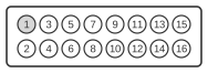
| Nintendo Wii Pin | Name | Description |
|---|---|---|
| 1 | AL | Audio Left |
| 2 | AR | Audio Right |
| 3 | VC | Video (Composite) |
| 4 | PWR | +5v |
| 5 | GND | Ground |
| 6 | GND | Ground |
| 7 | Y / R / Luma | Red (PAL), Luma (NTSC), or Component Y |
| 8 | Mode | Mode select. If shorted with pin 10, pin 7, 9 and 11 will output Component YPbPr |
| 9 | PB / G / Chroma | Green (PAL), Chroma (NTSC), or Component Pb |
| 10 | Mode | Mode select. If shorted with pin 8, pin 7 9 and 11 will output Component YPbPr (both PAL and NTSC) |
| 11 | Pr / B | Blue (PAL) or Component Pr |
| 12 | GND | Ground |
| 13 | PWR | +12v |
| 14 | DATA | Data line 1 (Used to change the number of lines) |
| 15 | DATA | Data line 2 (Used to change from interlaced to progressive) |
| 16 | DATA | Data line 3 (Used to change from 4:3 to letterbox and 16:9) |
Signals
- AL — Analogue audio, left channel.
- AR — Analogue audio, right channel.
- VC — Composite video (CVBS); present on all regional variants.
- PWR (+5 V) — +5 V supply line.
- GND — Signal ground (pins 5, 6, and 12).
- Y / R / Luma — Carries Red (RGB, PAL), Luma/Y (S-Video, NTSC), or Component Y when mode pins are shorted.
- Mode (pins 8 and 10) — Mode-select lines; shorting both pins together switches pins 7, 9, and 11 from their regional default (RGB or S-Video) to YPbPr component output on all regions.
- PB / G / Chroma — Carries Green (RGB, PAL), Chroma/C (S-Video, NTSC), or Component Pb when mode pins are shorted.
- Pr / B — Carries Blue (RGB, PAL) or Component Pr when mode pins are shorted; no S-Video equivalent on this pin.
- PWR (+12 V) — +12 V supply line; on PAL consoles this rail is used by SCART-equipped televisions for automatic input switching.
- DATA (pins 14–16) — D-Terminal data lines (Japanese market only). Pin 14 signals the number of scan lines (0 V = 525 lines; 2.2 V = 750 lines; 5 V = 1125 lines). Pin 15 signals progressive or interlaced scan (0 V = interlaced; 5 V = progressive). Pin 16 signals aspect ratio (0 V = 4:3; 2.2 V = 4:3 letterbox; 5 V = 16:9). These lines are non-functional on PAL consoles.
Notes
- Nintendo states that the Wii console will not work with any AV cable other than the model supplied with it or the separately available component video cable.
- The included Wii AV Cable carries composite video and stereo audio only. Component video (YPbPr, up to 480p) requires the separately sold Wii Component Video Cable, which shorts pins 8 and 10 to switch the video output mode.
- On PAL consoles, the +12 V on pin 13 drives the SCART auto-switching function on compatible televisions.
- The D-Terminal data lines (pins 14–16) are present on the connector hardware of all Wii consoles but are operationally non-functional on PAL units.
- The Wii mini (RVL-201) outputs composite video only and is physically incompatible with component cables.
- Nintendo did not publish a public pin-level specification for this connector.
References
- Wii Operations Manual (Model No. RVL-001), English — Nintendo Co., Ltd. / Nintendo of America, Inc., 2006