
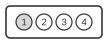
4 pin CONNECTOR at the computer
| Pin | Name | Description |
|---|---|---|
| 1 | GND | Ground |
| 2 | key | Key |
| 3 | GND | Ground |
| 4 | +6V | +6 Vdc |
The IBM PC AT (Model 5170) motherboard carries a 4-pin keyed Berg strip connector, designated J21, that supplies power to an external backup battery. Defined in the IBM PC AT Technical Reference (March 1984), this connector maintains the CMOS real-time clock circuit when the main power supply is off. The battery voltage is 6 Vdc, not the 5 V rail used elsewhere on the board. The connector housing includes a physical key on pin 2 to prevent incorrect insertion.
Signals
- GND — Ground return for the battery circuit (pins 1 and 3)
- key — Physical keying pin; no electrical signal
- +6V — +6 Vdc battery supply to the CMOS/RTC circuit
Notes
The connector is a keyed 4-pin Berg strip (0.1 inch / 2.54 mm pitch). Pin 2 carries no electrical signal; it is a mechanical key to ensure correct polarity. Many OEM AT-compatible clones adopted the same 4-pin layout but with varying polarity assignments, so always verify against the specific board’s documentation before connecting an external battery pack.