
The motherboard IrDA header is an internal connector that brings UART serial transmit and receive signals to a header for attachment of a Serial Infrared (SIR) module. The governing physical-layer standard is the IrDA Serial Infrared Physical Layer Specification (IrPHY), which defines SIR operation as asynchronous half-duplex at 2.4 to 115.2 kbps using Return-to-Zero Inverted (RZI) modulation with a 3/16-bit-period pulse width at approximately 875 nm. Because SIR reuses standard UART logic, the motherboard header is essentially a UART TX/RX pair routed to a 5-pin or 6-pin header. Intel’s Front Panel I/O Connectivity Design Guide (Order A29286) defines a common 2×3-pin layout for ATX boards, but the header arrangement is not universal and varies between manufacturers.
NOTE: This connector is not standard and may vary on different motherboards.
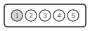
5 PIN IDC MALE at the motherboard
Layout 1
| Pin | Name | Description |
|---|---|---|
| 1 | +5v | Power |
| 2 | n/c | Not connected |
| 3 | IRRX | IR Module data received |
| 4 | GND | System GND |
| 5 | IRTX | IR Module data transmit |
Layout 2
| Pin | Name | Description |
|---|---|---|
| 1 | +5v | Power |
| 2 | IRRX | IR Module data received |
| 3 | GND | System GND |
| 4 | IRTX | IR Module data transmit |
| 5 | CIRRX | Consumer IR Receiving |
Signals
- +5v — 5 V supply for the IR module; powers the transceiver electronics.
- IRRX — Serial infrared receive signal; UART serial input carrying data from the IR module to the motherboard.
- IRTX — Serial infrared transmit signal; UART serial output carrying data from the motherboard to the IR module.
- GND — System ground reference.
- n/c — No connection; pin position reserved or used for keying on some variants.
- CIRRX — Consumer IR receive signal; present on some OEM variants to support remote-control reception independent of the SIR channel.
Notes
- The header layout is not standardised across manufacturers; two common single-row 5-pin variants are shown above. Intel’s Front Panel I/O Connectivity Design Guide additionally defines a 2×3-pin (6-pin dual-row) layout with Pin 1=IRRX, Pin 2=GND, Pin 3=GND, Pin 4=Key (no pin), Pin 5=IRTX, Pin 6=+5V.
- SIR operates at data rates from 2.4 kbps to 115.2 kbps; the physical layer uses RZI modulation with a 3/16-bit-period pulse width at approximately 875 nm wavelength.
- The header uses 2.54 mm pitch pins. Observe polarity when fitting an IR module; incorrect orientation may damage the transceiver or the motherboard circuitry.
- The CIRRX signal (Layout 2, Pin 5) is an OEM addition for consumer infrared (e.g. remote-control) reception and is not part of the IrDA SIR specification.