connector or cable wiring scheme devices for flashing cellular
phones
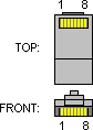
 8 pin RJ45 (8P8C)
female connector at the device
8 pin RJ45 (8P8C)
female connector at the device
 8 pin RJ45 (8P8C) male
connector at the cable
8 pin RJ45 (8P8C) male
connector at the cable
| Pin |
Signal |
Description |
Color |
| 1 |
+5V |
Switchable 5V Flash Supply |
Blue |
| 2 |
TX |
output, data to phone |
Red |
| 3 |
RX |
input, data from phone |
White |
| 4 |
CTS |
output, data to phone |
Gray |
| 5 |
RTS |
input, data from phone |
Brown |
| 6 |
M/C-BUS |
bi-directional 1 wire bus |
Yellow |
| 7,8 |
GND |
|
Green, Orange |
==Unibox, RJ48 connector=
| Pin |
Signal |
Description |
| 1 |
DCD |
input |
| 2 |
RxD |
input |
| 3 |
TxD |
output |
| 4 |
DTR |
output |
| 5 |
GND |
|
| 6 |
DSR |
input |
| 7 |
RTS |
output |
| 8 |
CTS |
input |
| 9 |
RI |
input |
| 10 |
+5V |
|
Griffin,
“Multi-box special” RJ45 connector pinout
| Pin |
Signal |
Description |
| 1 |
VBat |
|
| 3 |
BSI |
|
| 4 |
Rx |
|
| 5 |
Tx |
|
| 6 |
MBus |
|
| 7 |
GND |
|
UFS Tornado box RJ45
connector pinout
| Pin |
Name |
Description |
| 1 |
Vpp |
|
| 2 |
Gnd |
|
| 3 |
Mbus |
|
| 4 |
Txd |
|
| 5 |
Rxd |
|
| 6 |
Ibi |
|
| 7 |
P3v |
|
| 8 |
P6v |
|
Multi-Box JTAG connector
| Pin |
Signal |
Description |
| 1 |
Vbat |
|
| 2 |
Tx |
|
| 3 |
Rx |
|
| 4 |
TMS |
|
| 5 |
TCK |
|
| 6 |
TDI |
|
| 7 |
TDO |
|
| 8 |
GND |
|
Multi-Box UNI RJ45
connector
| Pin |
Signal |
Description |
| 1 |
Vcc +5V |
|
| 2 |
Tx |
|
| 3 |
Rx |
|
| 4 |
CTS |
|
| 5 |
RTS |
|
| 6 |
M-bus |
|
| 7 |
RES |
|
| 8 |
GND |
|
Nokia Flasher connector
| Pin |
Signal |
Description |
| 1 |
Bat+ |
|
| 2 |
BSI |
|
| 3 |
BTemp |
|
| 4 |
Tx |
|
| 5 |
Rx |
|
| 6 |
MBUS |
|
| 7 |
Vpp |
|
| 8 |
GND |
|
Notes
References
Category:Cellular
Phones Connectors