
This cable connects the Commodore 64 User Port to a parallel printer using the Centronics interface, which was developed by Centronics Data Computer Corporation in the early 1970s and introduced on their Model 101 dot-matrix printer. The C64 User Port exposes Port B (PB0–PB7) of CIA #2 (6526 chip, U2) on a 12×2 edge connector, providing eight bidirectional data lines plus handshake signals. Data bytes are placed on PB0–PB7 and latched into the printer by PA2 acting as the active-low /STROBE line, whilst FLAG2 receives the printer’s /ACK pulse and triggers a CIA interrupt to signal that the byte was accepted. The Centronics printer side uses the standard 36-pin Amphenol micro-ribbon connector, later formalised as the 1284-B connector in IEEE 1284-2000.
DZM 12 DREH to the C64 UserPort
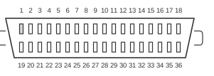 36 PIN CENTRONICS MALE to the Printer
| C64 | Dir | Printer | ||
|---|---|---|---|---|
| GND | 1,12,A,N | - | 19-30,33 | Ground |
| FLAG2 | B | IN | 10 | Acknowledge |
| PB0 | C | OUT | 2 | Data 0 |
| PB1 | D | OUT | 3 | Data 1 |
| PB2 | E | OUT | 4 | Data 2 |
| PB3 | F | OUT | 5 | Data 3 |
| PB4 | H | OUT | 6 | Data 4 |
| PB5 | J | OUT | 7 | Data 5 |
| PB6 | K | OUT | 8 | Data 6 |
| PB7 | L | OUT | 9 | Data 7 |
| PA2 | M | OUT | 1 | Strobe |
| GND | 3 | OUT | 31 | Initialize Printer |
Signals
- GND — Ground; multiple User Port pins (1, 12, A, N) connect to Centronics ground pins 19–30 and 33.
- FLAG2 — CIA #2 FLAG interrupt input (User Port pin B); receives the printer’s active-low /ACKNOWLEDGE pulse (Centronics pin 10), which triggers an interrupt to indicate the byte was accepted.
- PB0–PB7 — Port B bits 0–7 of CIA #2 (User Port pins C–L); carry the 8-bit parallel data byte to Centronics data lines 1–8 (pins 2–9). All lines are TTL-compatible with 1 kΩ pull-ups to +5 V on the printer side.
- PA2 — Port A bit 2 of CIA #2 (User Port pin M); drives the active-low /STROBE line (Centronics pin 1) to latch the data byte into the printer. Maximum strobe interval is 500 µs; ACKNOWLEDGE pulse width from the printer is 4 µs.
- GND (pin 3 → Centronics 31) — User Port RESET pin 3 wired to Centronics pin 31 (INPUT PRIME / /INIT) to allow printer initialisation.
Notes
- The C64 User Port edge connector has bottom-row pins labelled A–N (skipping I and O) and top-row pins 1–12.
- The User Port supplies +5 V at up to 100 mA (pin 2) and +9 VAC at up to 50 mA (pins 10–11); these are not used by this cable.
- A cartridge providing Centronics parallel support (such as TFCIII or Action Replay) may be required depending on the software driver used.
- The Centronics 36-pin micro-ribbon connector (Amphenol 57-30360) is defined as the 1284-B connector in IEEE 1284-2000. Compatibility Mode (SPP) — the original unidirectional Centronics handshake — is the mode used by this cable.
- Data direction for PB0–PB7 is controlled via CIA #2 Port B Data Direction Register at address $DD03; all bits should be set to output (1) for printer use.
References
- Commodore 64 Programmer’s Reference Guide (1983)
- C64/C64C Service Manual, March 1992 (PN-314001-02)
- Centronics Model 101A Printer Technical Manual (May 1978)
- Centronics Models 101/101A/101AL/102A/306 Specifications and Interface Information
- IEEE 1284-2000 — Standard Signaling Method for a Bidirectional Parallel Peripheral Interface for Personal Computers