
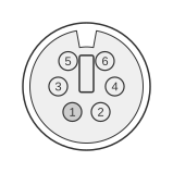
 6 pin mini-DIN male (PS/2 STYLE) connector to the PC
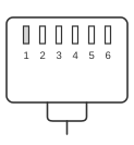 6 pin RJ12 (6P6C) male connector to the Mouse signal Receiver
The Gyration Gyro Point II is a cordless gyroscopic pointing device from the mid-to-late 1990s that communicates with the host PC via an RF receiver connected to the PS/2 mouse port. The PC-side connector follows the IBM PS/2 standard introduced in 1987: a 6-pin mini-DIN carrying Data, Clock, +5 V, and Ground on pins 1, 5, 4, and 3 respectively. The receiver side uses a 6-pin RJ12 (6P6C) connector, which is a proprietary Gyration interface; no public manufacturer specification for the RJ12 receiver connector has been published.
| PC Name | PC Pin | Direction | Mouse signal Receiver Pin | Mouse signal Receiver Name | Description |
|---|---|---|---|---|---|
| Data | 1 | ↔ | 1 | Data | |
| Gnd | 2 | — | 2 | N/C | |
| Gnd | 3 | ↔ | 3 | Gnd | |
| Vcc +5VDC | 4 | ↔ | 4 | Vcc +5VDC | |
| Clock | 5 | ↔ | 5 | Clock | |
| Gnd | 6 | — | 6 | N/C |
Signals
- Data — bidirectional serial data line; open-collector with pull-up to VCC; idle state high
- Gnd — signal ground; PS/2 pin 3 carries the active ground connection; pins 2 and 6 on the PC side are not connected at the receiver
- Vcc +5VDC — +5 V supply from the PC PS/2 port (+4.5 V to +5.5 V, maximum 275 mA); powers the RF receiver
- Clock — bidirectional clock line; open-collector with pull-up to VCC; idle state high; 10–16.7 kHz synchronous serial clock
- N/C — RJ12 pins 2 and 6 are not connected
Notes
The PS/2 6-pin mini-DIN connector is keyed to prevent incorrect insertion. Data and Clock lines are bidirectional open-collector; both must have pull-up resistors to VCC, which are normally provided by the PC motherboard. The RJ12 (6P6C) connector on the receiver side is a Gyration-proprietary interface; the pin assignments for that connector are not covered by any published standard.