
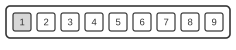
 9 pin Sony Playstation special connector
The Mad Catz Dual Force 2 is a third-party programmable controller for PSX, PSOne, and PS2 consoles, released in the late 1990s. It uses the standard 9-pin Sony PlayStation proprietary serial connector, which is not a standard D-sub shell. The electrical interface employs an SPI-like serial bus running at 250 kHz, LSB-first, with CPOL=1 CPHA=1 polarity; the DATA and ACK lines are open-drain and require pull-up resistors. Sony never published an official interface specification for this connector; the protocol is documented through reverse engineering.
| Pin | Name | Description |
|---|---|---|
| 1 | DATA | Brown wire = Pin 1 on control board |
| 2 | CMD | Orange wire = Pin 2 on control board |
| 3 | 9VDC | White wire = Pin 4 on control board |
| 4 | GND | Purple + Black wire: Purple = Pin 8 on control board. Black = pin 3 on control board |
| 5 | VCC | Red Wire = pin 5 on control board |
| 6 | ATT | Yellow wire = pin 6 on control board |
| 7 | CLK | Blue wire = pin 7 on control board |
| 8 | N/C | Not connected (not used in PSX or PS2 controls and often not present in plug) |
| 9 | ACK | Green Wire = pin 9 on control board |
Signals
- DATA — Serial data from controller to console; open-drain, active-low, LSB first.
- CMD — Serial command from console to controller.
- 9VDC — Motor power supply (+7.5 V nominal) for rumble actuators.
- GND — Signal and logic ground. Both purple and black internal wires connect to this pin; if the black wire is disconnected, the vibration motors run continuously.
- VCC — Logic supply voltage (+3.5 V).
- ATT — Chip select / attention line (/CSn); active-low, asserted by the console to address the controller.
- CLK — Serial clock (SCK), 250 kHz, CPOL=1 CPHA=1.
- N/C — Not connected; this pin is absent or unused in PSX and PS2 controllers and is often not present in the plug.
- ACK — Acknowledge from controller to console; open-drain, active-low.
Notes
- Compatible with PSX, PSOne, and PS2 consoles.
- The internal control board pins are numbered; pin 1 is identified by a square PCB pad. With the lower casing removed and the board viewed from the underside, pins run sequentially from left to right (nine in total).
- Both the purple and black internal wires connect to pin 4 (GND). If the black wire is absent or disconnected, the rumble motors will operate continuously.
- The connector shell is a Sony proprietary form factor and is not interchangeable with any standard D-sub connector.