
The Nintendo Entertainment System (NES — the Famicom in Japan, 1983; North America, 1985) and the Super NES (SNES, 1990/1991) standard controllers report their buttons as a serial bitstream. The console latches all button states into a parallel-in/serial-out shift register — a 4021 — inside the pad, then clocks the stored bits out one at a time on a single data line. A pressed button reads as a logic 0. The NES pad uses one 4021 (8 buttons); the SNES pad chains two (16 bits, of which 12 are buttons). Both run on 5 V logic.
NES controller
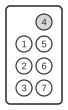
- +5VDC supply
- D3 (extra data in at $4017; unused by the standard pad)
- D4 (extra data in at $4017; unused by the standard pad)
- GND
- CLK (clock)
- Latch
- Data out
The NES starts the show by sending a high pulse down the Latch line, which makes the 4021 (8-bit shift register) inside the controller grab and store the state of all buttons.
Then the NES sends a series of eight low pulses down the CLK line, which makes the controller shuffle bits (one for each CLK pulse) down the Data Out line according to which buttons were pressed when latched. A low bit on the Data Out line means the button is pressed.
NES button order (one per clock pulse): A, B, Select, Start, Up, Down, Left, Right.
SNES controller
The SNES controller uses the same latch/clock/data protocol, but chains two 4021 registers to shift out 16 bits — 12 buttons followed by four bits that always read 0. Its 7-pin plug:
| Pin | Signal | Description |
|---|---|---|
| 1 | +5 V | Power |
| 2 | Clock | Shift clock from the console |
| 3 | Latch | Latch / poll pulse from the console |
| 4 | Data | Serial data, controller → console |
| 5 | — | Second data line (used by some peripherals) |
| 6 | I/O | General-purpose I/O (peripherals such as the Super Scope) |
| 7 | GND | Ground |
SNES button order (16 clock pulses): B, Y, Select, Start, Up, Down, Left, Right, A, X, L, R, then four bits that always read 0.
Notes
- On the NES, pins 2 and 3 are the console port’s extra data-in lines (D3 and D4, read at register $4017). The standard pad leaves them unconnected; peripherals use them — for example, the Zapper light gun returns its light-sense and trigger states on these lines, and the Arkanoid paddle also uses the port’s extra pins.
- A button reads as logic 0 (low) when pressed; the console typically polls the controller once per video frame.
- The SNES needs 16 bits because its pad has 12 buttons, more than a single 4021’s 8 stages; the NES, with 8 inputs, uses one 4021.
References
- Texas Instruments CD4021B — CMOS 8-Stage Static Shift Register datasheet — the parallel-in/serial-out register used inside the controllers.
- NXP HEF4021B — 8-bit static shift register datasheet — the parallel-load (latch) and clocked-shift behaviour.