
The Nintendo GameCube controller port is a proprietary 7-pin connector introduced with the GameCube console in 2001. It carries a single bi-directional serial data line operating at approximately 3.43 V logic (measured on PAL hardware; 3.3 V is also commonly cited), a dedicated 5 V supply for the rumble motor, a 3.43 V logic supply rail, and three ground returns including the cable shield. Communication uses a half-duplex asynchronous serial protocol (JoyBus) at roughly 250 kbit/s: the console sends a 24-bit command and the controller responds with a 64-bit packet encoding buttons, D-pad, analogue sticks, and shoulder triggers, with a polling interval of approximately 6 ms. Nintendo never published a public specification for this connector or protocol.
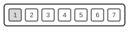 Seven (7) pin Nintendo GameCube controller connector.
| Pin | Color | J1 | Function |
|---|---|---|---|
| 1 | Yellow | 2 | 5V power supply (used by rumble motor). |
| 2 | Red | 3 | DATA line: bi-directional data to/from console, pull-up to 3.43V |
| 3 | Green | 4 | Ground. |
| 4 | White | 5 | Ground (Extrme Skillz GC to USB interface has pins 3+4 wired as common ground). |
| 5 | - | - | Unknown. |
| 6 | Blue | 1 | 3.43V logic supply. |
| 7 | Black | 6 | Cable shielding / ground. Usually the same ground of pin 3. |
Signals
- 5 V (Pin 1) — Power supply for the rumble motor only; not the logic supply rail.
- DATA (Pin 2) — Single bi-directional serial data line, active-high at 3.43 V; an open-collector pull-down arrangement with a 1 kΩ pull-up is recommended. Bit encoding: logic 0 = 3 µs low + 1 µs high; logic 1 = 1 µs low + 3 µs high (4 µs per bit). Rumble is controlled by bit 0 of the console’s command word.
- GND (Pins 3, 4, 7) — Three ground returns; pin 7 is the cable shield and is typically common with pin 3. Pin 4 is a separate ground return; adapters such as the Extreme Skillz GC-to-USB interface wire pins 3 and 4 together as a common ground.
- NC (Pin 5) — Function unknown; not connected in known implementations.
- 3.43 V (Pin 6) — Logic supply for the controller electronics. The 3.43 V figure is the measured value on PAL hardware; 3.3 V is the nominal logic level cited in general references and both values appear in practice.
Notes
- The J1 column gives the corresponding pin number inside the controller’s internal connector.
- The logic voltage on pin 6 is measured at 3.43 V on PAL hardware; 3.3 V is the nominal value and both appear in practice — the difference is not functionally significant.
- The connector is keyed and proprietary to Nintendo; it is not compatible with any industry-standard connector form factor.