
camera connector or camera cable scheme
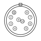 10 pin DIN female connector at the videocamera (facing you)
The VHS portable video camera 10-pin connector is the EIAJ CCJ (Camera Cable type J), standardised by the Electronic Industries Association of Japan in the late 1960s. The physical connector is a Hirose RM15-D series 10-pin circular DIN with a threaded lock ring; mating inline and panel-mount jacks are the RM15TJD-10S and RM15TRD-10S respectively. First introduced by Sony on early black-and-white cameras, it was subsequently adopted by JVC, Panasonic, Akai, and most other manufacturers of portable video equipment through the 1980s. The connector carries +12 V DC power, composite video, and audio signals simultaneously, and also supports several manufacturer-specific control lines whose assignments varied between brands and even between models from the same manufacturer.
| Pin | Name | Alt Name 1 | Alt Name 2 | Alt Name 3 |
|---|---|---|---|---|
| 1 | video out | video in/out | ||
| 2 | video gnd | |||
| 3 | serial data | |||
| 4 | tally and clock | reset in | ||
| 5 | audio out right | standby out | audio in | |
| 6 | pause | |||
| 7 | audio out | audio out left | ||
| 8 | audio gnd | |||
| 9 | power gnd | |||
| 10 | +12V power |
Notes
The connector body is keyed with a notch to prevent incorrect orientation. The “Name” column reflects the most commonly documented wiring, drawn from JVC equipment manuals; the three “Alt Name” columns capture the principal variants found on other manufacturers’ equipment. There is no single universal wiring standard: Sony, Panasonic, JVC, and Akai all used different signal assignments on physically identical connectors, so compatibility between brands cannot be assumed even when the plug fits. Power is supplied at +12 V DC, typically at 0.5–2.0 A. The connector operates in four modes depending on the equipment state: TV/REC, TV/PLAY, CAM/REC, and CAM/PLAY.
Signals
- video out / video in/out — composite video signal (pin 1); the most common wiring treats this as camera output only, though some decks use the same pin bidirectionally
- video gnd — signal ground for the composite video line (pin 2)
- serial data — manufacturer-specific serial control bus (pin 3); function varies by brand
- tally and clock / reset in — manufacturer-specific control line (pin 4); used for tally signalling, clock, or deck reset depending on equipment
- audio out right / standby out / audio in — audio or control line (pin 5); assigned differently across manufacturers and modes
- pause — remote pause/record control signal (pin 6)
- audio out / audio out left — primary audio output from the camera (pin 7)
- audio gnd — signal ground for the audio line (pin 8)
- power gnd — return path for the +12 V DC supply (pin 9)
- +12V power — DC supply from the video deck or power base to the camera, typically 0.5–2.0 A (pin 10)
References
- Hirose RM15TJD-10S — 10-pin circular connector datasheet — Hirose Electric Co., Ltd.
- Hirose RM15TRD-10S — 10-pin panel-mount connector datasheet — Hirose Electric Co., Ltd.
- EIAJ CCJ (Camera Cable, type J) 10-pin connector standard — Electronic Industries Association of Japan.