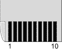
 Memory Stick - Memory Stick
Pro - 10 pin connector
Memory Stick - Memory Stick
Pro - 10 pin connector
| Pin | Signal | Direction | Description |
|---|---|---|---|
| 1 | VSS | ||
| 2 | BS | IN | Bus State. Indicates the Bus State (0-3) on the SDIO and the timing to start signal transfer. |
| 3 | DATA1 | IN/OUT | Data |
| 4 | SDIO/DATA0 | IN/OUT | Serial Data In-Out / Data. Transfer direction and types of data change depending on the Bus State. |
| 5 | DATA2 | IN/OUT | Data |
| 6 | INS | OUT | |
| 7 | DATA3 | IN/OUT | Data |
| 8 | SCLK | IN | Serial CLocK. A host product outputs signals on BS and SDIO af failing edge and inputs (latches) at rising edge. SCLK is always output during BS1-BS3. |
| 9 | VCC | ||
| 10 | VSS |
Notes
- both Pin 1 and Pin 10 shall be connected to VSS.
- Memory Stick, Memory Stick Duo, MagicGate, MagicGate Memory Stick, MemoryStick PRO are registered trademarks or trademarks of Sony Corporation.
References
- Memory Stick Standard (PDF link)